Preventing Helical Spring Corrosion
Helical Spring Design Resources – Spring Materials
The effect of a corrosive environment on helical spring performance is difficult to predict with certainty. General corrosion, galvanic corrosion, stress corrosion and corrosion fatigue reduce the life and load-carrying ability of springs. The two most common methods employed to combat effects of corrosion are to specify materials that are inert to the environment and to use protective coatings. Use of inert materials affords the most reliable protection against deleterious effects of all types of corrosion; however, this is often costly and sometimes impractical. Protective coatings are often the most cost-effective method to prolong spring life in corrosive environments. In special situations, shot peening can be used to prevent stress corrosion, and cathodic protection systems can be used to prevent general corrosion.
Coatings may be classified as galvanically sacrificial or simple barrier coatings. Sacrificial coatings for high carbon steel substrates include zinc, cadmium (and alloys thereof) and, to a lesser degree, aluminum. Due to its toxicity, cadmium coating should only be specified when absolutely necessary. Because sacrificial coatings are chemically less noble than steel, the substrate is protected in two ways. First, the coating acts as a barrier between substrate and environment. Second, galvanic action between coating and substrate cathodically protects the substrate. This characteristic allows sacrificial coatings to continue their protective role even after the coating is scratched, nicked or cracked. The amount of damage a sacrificial coating can sustain and still protect the substrate is a function of the size of the damaged area and the efficiency the electrolyte involved. Use of conversion coatings, such as chromates, lengthens the time of protection by protecting sacrificial coatings. Salt spray (fog) is an accelerated test and results may, or may not, correlate with corrosive activity in the actual environment. The test is useful as a control to ensure the coating was applied properly.
Metallic coatings are normally applied by electroplating. Since most high-hardness steels are inherently very susceptible to hydrogen embrittlement, plating must be carried out with great care to minimize embrittlement and subsequent fatigue failure. A baking operation after plating is also essential. The designer should observe these points during design and specification:
- Minimize sharp corners and similar stress-concentration points in design.
- Keep hardness as low as possible.
- Keep operating stress down, in accordance with lowered hardness value.
- Specify plating thickness, depending upon requirements.
- Specify that parts be baked after plating.
- Consider use of HEP™ strips to monitor the plating operation.
- Residual stress from forming operations must be reduced by stress relief at the highest practical temperature. Otherwise the combined effect of residual tension and hydrogen absorbed during plating can induce cracking even before plating is completed.
Similar cautions apply if acid cleaning procedures are contemplated.
Mechanical plating provides an effective means of zinc or cadmium protection with minimum hydrogen embrittlement. It is particularly recommended where parts have high residual stress, have been hardened above HRC48 and are used with high static loads. The process can only be applied to parts that do not tangle and have a clean, fully accessible surface. Hydrogen embrittlement, although unlikely, is still possible if parts are cleaned by pickling. When appropriate, coatings of zinc, tin, cadmium, or an alloy of cadmium can be applied by mechanical plating processes.
Cadmium, zinc or, more commonly, alloys of the two can be applied to steel spring wire during its production and, under some circumstances, this alternative is highly desirable. It is best suited to small-diameter wire and, in general, for the production of springs not requiring grinding.
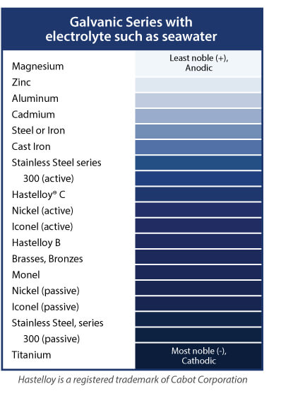
Helical springs are almost always in contact with other metal parts. In a corrosive environment, it is important that the spring material be more noble than components in contact with it. The Order of Nobility chart, shows a partial list of alloys in increasing order of nobility. When any two alloys are placed in contact in the presence of an electrolyte, the less noble alloy will be attacked. The attack will be significantly more vigorous than that of the electrolyte acting by itself.
Order of Nobility

The list of coatings that protect the base material by acting as a barrier to the environment is extensive and increases as new finishes and techniques are developed.
While coatings frequently increase in effectiveness as their thicknesses are increased, cautions are in order. Tendencies to crack increase as coating thickness increases, and the coating increases the size of the spring. For example, coatings increase the solid height and diametral clearances required for compression springs. Brittle coatings, such as epoxy, can chip under impact, leaving unprotected spots. Tough coatings, such as vinyl, resist chipping, but bruises, tears or abrasions can expose the base material and trap corrosive agents. This allows corrosion to continue after exposure and, in these circumstances, coated springs occasionally exhibit shorter lives than uncoated springs.
Frequently, oils, waxes or greases provide adequate protection. Effectiveness of these coatings is often dependent on the nature of the surface to be protected. In general, lustrous or smooth parts will not retain oils, and waxes, paraffin-based oils or greases are recommended. Steels can be phosphate-coated by a conversion process. Phosphate coatings have a high retention for oils, greases or paints. The combination of a phosphate and oil coating becomes a corrosion inhibitor more effective than either of the components. A similar effect is obtained by retaining or deliberately forming oxides on metal surfaces to hold corrosion inhibitors or lubricants. Oil-tempered spring wire is a notable example of this technique.
Content Copyright Spring Manufacturers Institute, Inc.
This information is attributed to, and provided courtesy of, the Spring Manufacturers Institute, Inc. (SMI). Newcomb Spring and SMI provide this as advisory information only, and disclaim any and all liability of any kind for the use, application or adaption of material published on this web site.